Ultra Clinch Technology
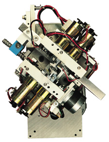
The CS-400E with Cut & Clinch mechnism is the only machine on the market that offers programmable lead length and clinch angle. It employs a cut & clinch mechanism consisting of two cutter assemblies; one fixed and one movable. Each assembly comprises an inner and outer cutter. The complete mechanism is mounted on a turntable which can rotate a full 360 degrees in .5 degree increments. The component leads pass through the center of the holes of the inner cutters. The outer cutters then rotate over the holes, first cutting then bending the leads. In normal operation, both leads are cut and clinched in one operation. The CS-400E can be programmed to clinch leads inward, outward, or sideways. |
|
Ultra Clinch Cutter |
|
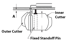 |
Lead LengthThe cutter assembly can be programmed to move up or down around the fixed standoff pin to achieve the ideal lead length (dimension"A"). |
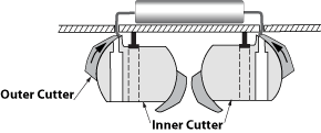 |
Clinch AngleThe outer cutters rotate over the inner cutters to cut the leads and produce the specified clinch angles. Each outer cutter can clinch its lead to any of ten programmable angles. |
|
|
|
Miniature Footprint
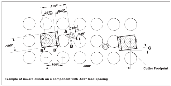
The CS-400E's footprint is so small that it is virtually invisible to adjacent leads, even on dense boards.
Two stationary pins provide support for the PCB, and are the only items to actually contact the board. These are represented by the cross-hatched circles “A”. Section “B” indicates the area on each cutter that will come within .040” of the underside of the board during the cutting action. These areas do not contact the board.
“C” represents the angle between the component center line and the direction of lead clinching, either inward or outward. The figure below shows this angle for a one half inch part. Refer to the table below for other component spacings.
“D” shows an extension of the normal footprint that would occur if the customer chose to adjust the cutters for an exaggerated lead bend. This would be necessary only for large leads (.40” copper) in oversized holes.
A matrix of holes on a .100” grid is shown in the figure below to illustrate the effect that the 400E footprint would have on a very dense board.
Clinch Direction VS. Component Lead Spacing
The cutters can be programmed to clinch the leads in an inward or outward direction for densely packed boards.
CS-400C/D/E Cutter Selection
Contact Systems™ Products
 Current Products
 - CS-400E Cut & Clinch Inserter
 CS-400E Video Library
 Cut & Clinch Technology
- Dual Spot Projection
- Ergonomic Design
- Specifications
- Component Delivery/Accessories
- Server Solution
- Retrofits
- CS-400E Cutter Selection Guide
- Cut & Clinch Exchange Program
- CS-400E Training Course
- CS-400E Inserter Remanufactured
- Previous Products
- Attention CS-400C and D Users
-
 SMT Placement Machines
 - Current Products
- C5 Series
- Previous Products
- 3 Series
- C5 Series (First Generation)
-
Contact Systems™ by Versatec
- Remanufacturing
- Pre-Owned Equipment
- Contact Systems™ Product History
- Customer Support
- Warranty and Service Plans
- Technical Support
- Spare Parts Supply
- Training
-
 About Versatec
 Site Map
  Video Library
  PDF Library
Contact Info Contact Sales Contact Technical Support
